Check out the new MinnowBoard.org website for the most up-to-date information on the MinnowBoard Turbot and the MinnowBoard.org Community.
Projects/Maker TFTLCD
In a previous example (Projects/Maker charLCD), you found that you could drive an LCD display with relative ease. However, you may be interested in displaying more than just text in your project. To display full-color images, you'll want to incorporate a more powerful display into your project. We'll be working with a thin-film-transistor liquid-crystal display (or TFTLCD for the acronym inclined) to display a wide variety of images for your project.
Contents
Difficulty
Hardware
Supplies
What you'll need to complete this project:
- 1 TFT LCD Display (find some samples here)
- 6 Male-to-Male cables
- 6 Female-to-Male cables
- Breadboard
- A MinnowBoard MAX with software prerequisites installed (see prep)
Wiring
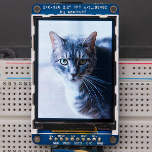
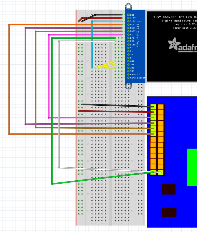
Compared to LEDS, a char LCD, or buttons, a TFT LCD is complex. Make sure to double check your wiring if something isn't working. The TFT LCD model we're working with is the 2.8 inch ILI9341 from Adafruit. The base layout has these connections:
- TFT LCD Pin 1 (GND) --> Ground
- TFT LCD Pin 2 (5v) --> 5v PWR
- TFT LCD Pin 3 (3v out) --> Some breadboard row (see diagram for clarification)
- TFT LCD Pin 4 (SPI CLK) --> Minnowboard Pin 11 (SPI CLK)
- TFT LCD Pin 5 (SPI MISO) --> Minnowboard Pin 7 (MISO)
- TFT LCD Pin 6 (SPI MOSI) --> Minnowboard Pin 9 (MOSI)
- TFT LCD Pin 7 (CS) --> Minnowboard Pin 5 (CS)
- TFT LCD Pin 8 (D/C) --> Minnowboard Pin 25 (GPIO)
- TFT LCD Pin 9 (RST) --> Minnowboard Pin 26 (GPIO)
- TFT LCD Pins 15, 16, 17 (IM3, IM2, IM1) --> 3v out row (see diagram for clarification)
If the power is wired correctly, the screen will turn on, being completely blank. Here's a diagram of the final result:
Here's a more detailed explination of the function of each pin
- SPI CLK
- This pin is what synchronizes data transmission between the Minnowboard and the SPI device. The signal is generated by the Minnowboard determining the data transmission speed, and is received by the TFT LCD.
- SPI MISO
- Master-in-Slave-out is the pin that allows the Minnowboard to get data from the TFT LCD device. Having a separate line for sending and receiving allows SPI to be full-duplex, being able to send and receive simultaneously.
- SPI MOSI
- Master-out-Slave-in is the pin that allows the Minnowboard to send data to the SPI peripherals, such as the TFT LCD.
- CS
- This is the chip select pin, which allows the Minnowboard to select different devices on the SPI bus to communicate with. This project only requires one device, so no special code is needed for the chip select.
- D/C
- The data / command pin tells the device what kind of information is currently coming in. If it is pulled LOW, then it expects commands such as the initialization bits or the clear flag. If it is pulled HIGH, it will use the incoming bits as data for the display.
- RST
- The optional reset pin will clear the display in between images. If a program needs the screen to be operated in this way, it saves the SPI bus having to write an entire sequence to clear the whole screen.
- IM0, IM1, IM2, IM3
- These pins control the interface logic mode for the TFT LCD device. Depending on which combination of these pins are pulled HIGH and LOW, the device's interface mode changes in which registers are used and whether the SPI or 8-bit mode is active. To use the SPI bus, pull IM1, IM2, and IM3 to HIGH using the 3v out pin on the device.
Software
Libraries required
Python Imaging Library
The Python Imaging Library (found here) is needed to use the device. This library turns images into formats that can be read by the TFT LCD. Additionally, it can draw images and shapes from pure Python for display on the device. Installing the library is quite easy, although there are some issues you may encounter. After downloading the latest source package to your device, extract it and move into the directory:
 root@intel-corei7-64:~# tar -xvf package_you_downloaded.tar.gz
 root@intel-corei7-64:~# cd package_you_downlaoded
 root@intel-corei7-64:~# python setup.py install
If you receive a failure message looking something like this:
no such file or directory
#include <freetype/fterrors.h>
         ^
Then you may need to fix a small path issue in your libraries directory. Thankfully, that's easy, just create a symbolic link like so:
ln -s /usr/local/include/freetype2 /usr/local/include/freetype
ILI9341
A pure Python variant of this driver allows you to use the device entirely in userspace without worrying about kernel modules. You can get the driver from <SUBJECT LINK HERE>
SPI Driver
You will need to be able to access the SPI bus on your device, which requires a driver to be active. Checking for the driver is as simple as running a few commands. First if you run this:
root@intel-corei7-64:~# ls /dev/spi*
and see this error message:
ls: cannot access /dev/spi*: No such file or directory
then you don't have access to the SPI device. To get access on the Minnowboard, you'll need the SPI driver package. If you've got the maker repository, it comes with the maker python package.
Installing the module
Just to into the spidev directory from the main minnow_max_maker directory
cd low_speed_spidev
And then make the module
make
Once you're done, you'll have the module in the directory. Insert it with:
insmod low_speed_spidev.ko
If you encountered an error, you may need to finish building the kernel scripts. To do this, go to the kernel directory and make them with
cd /usr/src/kernel
make scripts
Then try the module again.
Sample file: disp.py
If you've set up the wiring correctly and have the prerequisite software installed, you can try running the sample file that comes with the python package. Just run it like so:
python disp.py
And you should see shapes and text on your TFT LCD! If you don't, review your wiring and make sure the script didn't throw any errors during execution. As for the code, most of the disp.py file is dealing with the python imaging library, but most of the relevant scripting is simple:
# Get the Python Imaging Libraries for drawing shapes and working with images
import Image
import ImageDraw
import ImageFont

# Get our driver and GPIO libraries
import pyDrivers.ILI9341 as TFT
import Adafruit_GPIO.GPIO as GPIO
import Adafruit_GPIO.SPI as SPI


# Minnowboard MAX configuration.
DC = 25
RST = 26
SPI_PORT = 0
SPI_DEVICE = 0

# Create TFT LCD display class.
disp = TFT.ILI9341(DC, rst=RST, spi=SPI.SpiDev(SPI_PORT, SPI_DEVICE, max_speed_hz=1000000))

# Initialize display.
disp.begin()

# Clear the display to a red background.
# Can pass any tuple of red, green, blue values (from 0 to 255 each).
disp.clear((255, 0, 0))

# Get a PIL Draw object to start drawing on the display buffer.
draw = disp.draw()

# Some shapes are drawn using the ImageDraw library, and are added to a buffer ...

# Write buffer to the screen
disp.display()
Once you've created the PIL object, the ImageDraw library opens up, and you can use any selection of the shape drawing commands as part of the draw object, such as
# Draw a purple rectangle with yellow outline.
# Command is ( (tuple_of_coordinates), outline=(R, G, B), fill=(R, G, B))
draw.rectangle((10, 90, 110, 160), outline=(255,255,0), fill=(255,0,255))
To see all the commands at your disposal, check out the library reference and try some out for yourself.

