Check out the new MinnowBoard.org website for the most up-to-date information on the MinnowBoard Turbot and the MinnowBoard.org Community.
MinnowBoard MAX
| Category | Feature |
|---|---|
| Core Logic |
|
| Memory |
|
| Video |
|
| Audio |
|
| I/O |
|
| Experimenter Features |
|
| Board Dimensions |
|
| Temperature Range |
|
| Power |
|
| Operating Systems | |
| System Boot Firmware | |
| Note: These features and specifications may be subject to change without notice. | |

MinnowBoard MAX is the second generation MinnowBoard (released in July 2014), updating and replacing the original MinnowBoard. The MinnowBoard MAX board has an upgraded 64-bit Intel®Atom™ E3800 (Bay Trail-I) processor with better graphics and revised I/O, shrinks the footprint by more than half, supports additional operating systems (Linux*, Android*, and Windows*) and significantly improves on the original board on price, performance, and energy consumption.


Contents
- 1 MinnowBoard MAX Board Layout
- 1.1 Power Plug
- 1.2 SD Card
- 1.3 Serial Console
- 1.4 High Speed UART1
- 1.5 High Speed UART2
- 1.6 D1 (LED)
- 1.7 D2 (LED)
- 1.8 HDMI
- 1.9 Ethernet
- 1.10 Low Speed Expansion Connector (Top)
- 1.11 High Speed Expansion Connector (Bottom)
- 1.12 Low Speed Signal Mapping
- 1.13 SPI Header to Firmware flashing J1
- 1.14 Power Connection J2 (SIP2_FAN)
- 1.15 Switch Jumper J5
- 1.16 SATA LED J6
- 1.17 SD Card Write Protect J7
- 1.18 RTC Battery Holder
- 1.19 GPIO for 1GB vs 2GB
- 2 Board Design Files
- 3 Cases
- 4 Accessories (Lures)
- 5 Known Issues
- 5.1 MinnowBoard-MAX Open Bugs (Bugzilla)
- 5.2 Weak HDMI signal causing some monitors to not work
- 5.3 MinnowBoard MAX not booting: only one blue LED (D1) on, other (D2) is off
- 5.4 CPU Strapping issues
- 5.5 LSE Pin 26 Change notification
- 5.6 Plate over High Speed Expansion Headers
- 5.7 Firmware
- 5.8 NVRam issue
- 5.9 Monitors
- 5.10 RTC
- 5.11 USB
- 5.12 UART dies with "Too much work for irq"
- 6 Export Information
MinnowBoard MAX Board Layout
Here are photos showing the MinnowBoard MAX board layout identifying key hardware items; items are described later in this section.

NOTE: On Rev A1 boards and beyond, FTDI serial pin 1 is nearest the SATA connector, but on A0 boards pin 1 is furthest away. (A0 boards are rare, and are only being documented for completeness.)

NOTE: Some items, such as the Real Time Clock battery pad are not populated when the boards are manufactured.

Power Plug
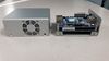
| The Minnowboard Max uses a 5.5 x 2.1mm barrel 5V power plug (+/- .25V or 4.75 - 5.25V), Recommended minimum 2.5A power supply. It is a Center Positive power supply, indicating that the center (tip) of the output plug is positive (+), the outer barrel is negative (-). The 2.5A recommendation is just a simple calculation of: 500mA (USB2) + 900mA (USB3) + 500mA (core) + 500mA (other peripherals) = 2400mA |
- Universal Power Supply from Digikey - 5V@3A - CUI EMSA050300-P5P-SZ
- Power Supply from Sparkfun - 5V@2A - TOL-12889
- Power Supply from SeeedStudio - 5V@2A SKU: POW06182B
NOTE: If you try to power both a MinnowBoard MAX AND a hard drive (spinning or SSD) off of the same power supply, please use a minimum of 3A supply, preferably 4A. Failure to do so will likely result in odd behavior of the MAX as the whole system may be pushed into a brown-out situation.
SD Card
The MinnowBoard has a microSD card interface built into the board. Some things to note:
- The microSD card goes in opposite to what most folks would expect, with the pads going upwards from the top of the board
- UHS is NOT supported. There is an option in the firmware to enable it if you would like to test it with your specific card, but it is unlikely to be stable.</br></br> Additional information on this can be found the firmware, or by going into the firmware menu and traversing to Main Menu -> Device Manager -> South Cluster Configuration -> LPSS & SCC Configuration -> DDR50 Capability Support
- Linux kernels 4.6 and higher have a change to the way they enumerate the mmcblk* devices. Before 4.6 the Linux kernel would (most likely) enumerate to mmcblk0 for the microSD card. With Linux kernel 4.6 and newer the microSD card will (likely) enumerate to mmcblk2. If you are using the device, please be aware of that change, and that the Linux kernel rarely guarantees enumeration of devices unless explicitly using a unique identifier (like the UUID for partitions). More information on the commit that causes this can be found here: http://git.kernel.org/cgit/linux/kernel/git/torvalds/linux.git/commit/?id=9aaf3437aa72ed5370bf32c99580a3fa2c330e3d
Serial Console
On your host computer, configure your terminal emulation software with these settings:
- /dev/ttyS0
- Baud rate: 115200
- Hardware Flow Control: No
- Bits: 8
- Stop: 1
The serial console port (UART0), located near the SATA connector at the top of the board, uses a 3.3v FTDI serial cable with a 6-pin connector. This is a reasonably common cable, also used on the Arduino Pro, Arduino Pro Mini and Arduino Lilypad. The cable connector typically has a triangle marking pin 1 (black wire).

 |
Pins and signal names are referenced from the cable:
|
NOTE: CTS,VCC, and RTS are not used on the debug UART header. The pinouts and connections are listed to facilitate locating and connecting a compatible adapter.
NOTE: On Rev A1 boards and beyond, FTDI serial pin 1 is nearest the SATA connector, but on A0 boards pin 1 is furthest. (A0 boards are rare, and are only being documented for completeness.)
6-Wire Serial Console
In this case, plug the connector in exactly as it's described in the primary layout.
Places that carry 6-pin FTDI connector cables include:
Configure your terminal emulation software with the same settings listed above.
4-Wire Serial Console
The serial console port (UART0) can also be used with a 3.3v FTDI serial cable with a 4-pin connector. This is a reasonably common cable, also used on the Arduino Pro, Arduino Pro Mini and Arduino Lilypad. If you are using one of the 4-wire adapters, here are the connections:
|
|
Pins and signal names are referenced from the cable:
|
Note:The RED wire is for power and is not internally connected on the MinnowBoard MAX. CTS,VCC, and RTS are not used on the debug UART header. The pinouts and connections are listed to facilitate locating and connecting a compatible adapter.
Places that carry 4-pin FTDI connector cables include:
Configure your terminal emulation software with the same settings listed above.
3-Wire Serial Console
The serial console port (UART0) can be used with a 3.3v FTDI serial cable with a 3-pin connector, for example Olimex USB-Serial-Cable-F. The same cable can used for debugging of a lot of other developer boards including HummingBoard, Raspberry Pi, Radxa Rock, Firefly-RK3288, and all of Olimex open source hardware boards OLinuXino. If you are using this cable, here are the connections:
NOTE: CTS,VCC, and RTS are not used on the debug UART header. The pinouts and connections are listed to facilitate locating and connecting a compatible adapter. Places that carry the appropriate Cable:
|

High Speed UART1
Available on the Low Speed Expansion this Uart is 16550 compatible and appears as /dev/ttyS4
CTS/RTS signaling is available
High Speed UART2
Available on the Low Speed Expansion this Uart is 16550 compatible and appears as /dev/ttyS5
CTS/RTS signaling is NOT available
D1 (LED)
D1 is the power indicator LED; when lit, power is being provided to the board.
D2 (LED)
D2 is the On/Off status indicator LED; when lit the CPU itself has come up and is working, the system is running.
Note: On later revisions of the board (A4+), this LED defaults to being on, but is controllable via a GPIO.
HDMI
The MinnowBoard MAX uses a Type D micro-HDMI connector. This is a standard port; cables and adapters are readily available from most electronics stores.
HDMI CEC
While the MAX (from a hardware perspective) supports HDMI CEC, the signal is, unfortunately, not passed completely from the micro-hdmi connector to the CPU. This means we lack the ability to directly manipulate CEC from the A1 and A2 revisions of the hardware. It has been proposed that this be resolved in a later revision of the board, but it is unknown at which point (if it ever is) rectified.
On the Turbot HDMI CEC is plumbed through to the SoC, and is connected to GPIO_S0_SC_58 (which should be Linux GPIO # 212 on older kernels and 468 on newer kernels)
Ethernet
The MinnowBoard MAX uses a Realtek RTL8111GS-CG PCIe based chipset to provide a 10/100/1000 Ethernet connection.
Low Speed Expansion Connector (Top)
The low speed expansion connector uses 0.1" (2.54 mm) male header pins in a 2 x 13 array, for a total of 26 pins. Pin 1 is in the row closest to the power connector, and closest to the board edge.
NOTES:
- All I/O on the Low Speed Expansion Connector is at 3.3V levels. THE PINS ARE NOT 5v TOLERANT
- For typical usage, the pins should be able to output up to 10mA, per pin. For normal operations you SHOULD NOT exceed that limit.
- Most LEDs tend to have a forward current need of more than 10mA, and thus may not work (directly) off of the LSE pins. It is suggested you use a transistor and drive it via the GPIO instead of direct connection.
LSE Layout
The Linux GPIO base address changed (by adding 256) from Linux kernel versions 3.17 to 3.18, so you'll need to know which kernel version you're using to select the correct GPIO numbers. This table lists the GPIO number for both the 3.17 and earlier kernels, and 3.18 and later kernels, for each pin on the connector:
| Description | Name | Pin | Linux GPIO# (≤3.17) | Linux GPIO# (≥3.18) | Linux GPIO# (≥3.18) | Linux GPIO# (≤3.17) | Pin | Name | Description |
|---|---|---|---|---|---|---|---|---|---|
| Ground | Gnd | 1 | 2 | Gnd | Ground | ||||
| +5V Power | VCC | 3 | 4 | +3V3 | + 3.3V Power | ||||
| SPI Chip Select 1 | GPIO_SPI_CS# | 5 | 220 | 476 | 481 | 225 | 6 | GPIO_UART1_TXD | UART Transmit |
| Master In / Slave Out | GPIO_SPI_MISO | 7 | 221 | 477 | 480 | 224 | 8 | GPIO_UART1_RXD | UART Receive |
| Master Out / Slave In | GPIO_SPI_MOSI | 9 | 222 | 478 | 483 | 227 | 10 | GPIO_UART1_CTS | CTS / GPIO |
| SPI Clock | GPIO_SPI_CLK | 11 | 223 | 479 | 482 | 226 | 12 | GPIO_UART1_RTS | RTS / GPIO |
| Clock / GPIO | GPIO_I2C_SCL (I2C #5) | 13 | 243 | 499 | 472 | 216 | 14 | GPIO_I2S_CLK | Clock / GPIO |
| Data / GPIO | GPIO_I2C_SDA (I2C #5) | 15 | 242 | 498 | 473 | 217 | 16 | GPIO_I2S_FRM (* Note issue) | Frame / GPIO |
| UART Transmit / GPIO | GPIO_UART2_TXD | 17 | 229 | 485 | 475 | 219 | 18 | GPIO_I2S_DO | Data Out / GPIO |
| UART Receive / GPIO | GPIO_UART2_RXD | 19 | 228 | 484 | 474 | 218 | 20 | GPIO_I2S_DI | Data In / GPIO |
| GPIO / Wakeup | GPIO_S5_0 | 21 | 82 | 338 | 504 | 248 | 22 | GPIO_PWM0 | PWM / GPIO |
| GPIO / Wakeup | GPIO_S5_1 | 23 | 83 | 339 | 505 | 249 | 24 | GPIO_PWM1 | PWM / GPIO |
| GPIO / Wakeup | GPIO_S5_2 | 25 | 84 | 340 | 464 509 |
208 253 |
26 | GPIO_IBL_8254 (*Notice) (MAX A2) I2SMCLK_GPIO (Turbot) |
Timer / GPIO I2S MCLK / GPIO |
NOTE: Pins 5-26 are shown above with their primary configuration, any pin may be switched to being a generic GPIO as well. This would give a total of 22 GPIOs, with two being PWM capable.
| Denotes Pins that have issues with firmware prior to 0.71 (8/13/2014 build) | |
| Denotes Pins that have been tested and work as expected. Remember to drive the pin to ground. |
High Speed Expansion Connector (Bottom)
The High speed expansion connector uses a TE Connectivity-compatible 60-pin header. We recommend using the 3-5177986-2 or the 60POS .8MM FH 8H GOLD part that rises 7.85mm. This permits using 3/8" standoffs at the corners for attaching a lure to the MinnowBoard MAX.
Link to connector used: http://www.digikey.com/product-detail/en/5177985-2/A99190CT-ND/1894007. mating connectors are listed at the bottom but include:
- A99196DKR-ND - CONN PLUG 60POS .8MM FH 5H GOLD
- A115336-ND - CONN PLUG 60POS DL BRD/BRD VERT
- 5179030-2-ND - CONN PLUG 60POS FH .8MM BRD-BRD
- 5177984-2-ND - CONN PLUG 60POS VERT FH .8MM
- A99215CT-ND - CONN PLUG 60POS .8MM FH 8H GOLD <-- Recommended connector
- A99209CT-ND - CONN PLUG 60POS .8MM FH 7H GOLD
- A99203CT-ND - CONN PLUG 60POS .8MM FH 6H GOLD
- A99196CT-ND - CONN PLUG 60POS .8MM FH 5H GOLD
- A99215TR-ND - CONN PLUG 60POS .8MM FH 8H GOLD
- A99209TR-ND - CONN PLUG 60POS .8MM FH 7H GOLD
HSE Layout
| Description | Pin | Pin | Description |
|---|---|---|---|
| Ground | 1 | 2 | Ground |
| mSATA_TX_P | 3 | 4 | mSATA_RX_P |
| mSATA_TX_N | 5 | 6 | mSATA_RX_N |
| +5V SB | 7 | 8 | +5V SB |
| mPCIE_REFCLK_P | 9 | 10 | USB_HOST_DP |
| mPCIE_REFCLK_N | 11 | 12 | USB_HOST_DN |
| Ground | 13 | 14 | Ground |
| mPCIE_TX_P | 15 | 16 | mPCIE_RX_P |
| mPCIE_TX_N | 17 | 18 | mPCIE_RX_N |
| +5V SB | 19 | 20 | +5V SB |
| EXP_I2C_SCL (I2C #6) | 21 | 22 | mPCIE_WAKEB |
| EXP_I2C_SDA (I2C #6) | 23 | 24 | mPCIe_CLKREQ3_B |
| Ground | 25 | 26 | Ground |
| EXP_GPIO1 | 27 | 28 | EXP_GPIO3 |
| EXP_GPIO2 | 29 | 30 | EXP_GPIO4 |
| +5V SB | 31 | 32 | +5V SB |
| EXP_GPIO6 (XDP_H_OBSDATA_A1) | 33 | 34 | EXP_GPIO5 (XDP_H_OBSDATA_A0) |
| EXP_GPIO7 (XDP_H_OBSDATA_A2) | 35 | 36 | EXP_GPIO8 (XDP_H_OBSDATA_A3) |
| Ground | 37 | 38 | Ground |
| XDP_H_PRDYB | 39 | 40 | XDP_H_PREQB_PB |
| PMC_RSMRST | 41 | 42 | FP_PWRBTN |
| +5V SB | 43 | 44 | +5V SB |
| PMC_CORE_PWROK | 45 | 46 | PMC_RSTBTN |
| PMC_PLTRST_R_V1P8 | 47 | 48 | ILB_RTC_TESTB |
| Ground | 49 | 50 | Ground |
| XDP Power Rail Status (3.3v ~250mA) | 51 | 52 | XDP_H_TRSTB |
| XDP Power Rail Status (1.8v ~250mA) | 53 | 54 | XDP_H_TCK |
| +V1P8A | 55 | 56 | XDP_H_TMS |
| +V1P8A | 57 | 58 | XDP_H_TDI |
| Ground | 59 | 60 | Ground |
Low Speed Signal Mapping
Interfacing to the various low speed I/O pins is in some cases a little non-obvious, particularly with how various aspects refer to the busses (hint: they don't always match up the way you would expect). The following sections should at least help de-mystify some of these interfaces.
GPIO Mapping
The Linux GPIO base address changed (by adding 256) from Linux kernel versions 3.17 to 3.18, so you'll need to know which kernel version you're using to select the correct GPIO numbers. This table lists the GPIO number for both the 3.17 and earlier kernels, and 3.18 and later kernels, for each pin on the connector:
| Name | Pin | Linux GPIO# (≤3.17) | Linux GPIO# (≥3.18) | Linux GPIO# (≥3.18) | Linux GPIO# (≤3.17) | Pin | Name |
|---|---|---|---|---|---|---|---|
| EXP_I2C_SCL (I2C #6) | 21 | 245 | 501 | ||||
| EXP_I2C_SDA (I2C #6) | 23 | 244 | 500 | ||||
| [...] | |||||||
| EXP_GPIO1 | 27 | 109 | 365 | 367 | 111 | 28 | EXP_GPIO3 |
| EXP_GPIO2 | 29 | 110 | 366 | 368 | 112 | 30 | EXP_GPIO4 |
| [...] | |||||||
| EXP_GPIO6 | 33 | 105 | 361 | 362 | 106 | 34 | EXP_GPIO5 |
| EXP_GPIO7 | 35 | 107 | 363 | 364 | 108 | 36 | EXP_GPIO8 |
| Denotes Pins that have issues with firmware prior to 0.71 (8/13/2014 build) | |
| Denotes Pins that have been tested and work as expected. Remember to drive the pin to ground. |
I2C Mapping
The externally facing I2C busses on the MinnowBoard MAX / Turbot are provided by the DesignWare IP block in the SoC. This typically ends up enumerating as bus #7 under Linux (you'll note it gets referred to as bus #5 above, that's because that's a hardware / firmware centric view and naming, not how the OS enumerates it). You can figure out what bus numbering you are looking at for sure by running:
# i2cdetect -l
i2c-0    unknown       i915 gmbus ssc                      N/A
i2c-1    unknown       i915 gmbus vga                      N/A
i2c-2    unknown       i915 gmbus panel                    N/A
i2c-3    unknown       i915 gmbus dpc                      N/A
i2c-4    unknown       i915 gmbus dpb                      N/A
i2c-5    unknown       i915 gmbus dpd                      N/A
i2c-6    unknown       DPDDC-B                             N/A
i2c-7    unknown       Synopsys DesignWare I2C adapter     N/A    <-- First one should be LSE
i2c-8    unknown       Synopsys DesignWare I2C adapter     N/A    <-- Second one should be HSE
#
You'll note in this case that that the two DesignWare devices are i2c-7 and i2c-8. Under normal enumeration the first of the two DesignWare adapters should be the LSE, the second should be the I2C in the HSE.
You'll also find that the DesignWare IP block does NOT support the SMBus Quick Write command, so if you see something like "Error: Can't use SMBus Quick Write command on this bus" when you try to use the bus, please remember to disable Quick Write support. For example, to find out what's on the specific I2C bus:
# i2cdetect  -y -r 7
     0  1  2  3  4  5  6  7  8  9  a  b  c  d  e  f
00:          -- -- -- -- -- -- -- -- -- -- -- -- --
10: -- -- -- -- -- -- -- -- -- -- -- -- -- -- -- --
20: -- -- -- -- -- -- -- -- -- -- -- -- -- -- -- --
30: -- -- -- -- -- -- -- -- -- -- -- -- -- -- -- --
40: 40 -- -- -- -- -- -- -- -- -- -- -- -- -- -- --
50: -- -- -- -- -- -- -- -- -- -- -- -- -- -- -- --
60: -- -- -- -- -- -- -- -- -- -- -- -- -- -- -- --
70: -- -- -- -- -- -- -- --
should list out devices that are detected on the bus. Noting we have seen, in some cases, some devices do not get detected, but are read/writeable directly to their addresses. You'll note in the above there is a single address detected, a device at address 40. If you have multiple devices they will show up independently. To directly read / write the those devices you would use `i2cget` and `i2cset`. You can see some example code of this from the Calamari examples at https://github.com/MinnowBoard/minnow-max-extras/blob/master/calamari/calamari-i2c-eeprom.sh
NOTE: The I2C pins have the same property as the pins in the Low Speed Expansion Header, in that their primary purpose is I2C, but can be switched to GPIO in the firmware.
NOTE: Rhproxy or Resource Hub Proxy Device ("MSFT8000") is a software device on Windows that exposes GPIO, I2C, SPI, and Serial busses to user mode applications and allows access hardware busses in user mode. (under Linux it will show up in sysfs as MSFT8000)
Learn more at https://sec.ch9.ms/sessions/winhec/slides/02_AccessHardwareBusesinUserMode_DevinWong_Final.pdf.
SPI Header to Firmware flashing J1
This is a pinned out port for external flashing of the boot SPI. Dediprog and Flyswatter devices have been tested and verified to work.
J1 Layout
| Description | Pin | Pin | Description |
|---|---|---|---|
| DDP_1V8 | 1 | 2 | Ground |
| DDP_SPI_CS | 3 | 4 | DDP_SPI_CLK |
| DDP_SPI_MISO | 5 | 6 | DDP_SPI_MOSI |
| 7 | 8 | DDP_IO3L |
Power Connection J2 (SIP2_FAN)
This is a 5V 2-pin pin out originally intended for a CPU fan. The single core (E3815) and the dual core (E3825) use passive heat sinks and do not, under normal circumstances, need a fan. While it's theoretically possible to pull upwards of 1A through this port, you should refer to the released schematics to verify this before attempting to use these power pins.
The pins have a 2.54mm pitch and Screw Terminals 2.54mm Pitch are an example of a compatible component.
NOTE: This is not populated on the Single, or Dual core boards as shipped.
J2 Layout
| Description | Pin | Pin | Description |
|---|---|---|---|
| +5VSB | 1 | 2 | Ground |
NOTE: If you are using an A0 board, the pinout is reversed. Always verify pin output, preferably with a multimeter, before using J2.
Switch Jumper J5
These pins are intended for power toggling via a remote switch or relay, fundamentally no different than pressing SW1.
NOTE: This is not populated, by default.
J5 Layout
| Description | Pin | Pin | Description |
|---|---|---|---|
| +5VSB | 1 | 2 | Ground |
SATA LED J6
J6 header allows an external LED to be connected to the SATA interface's activity signal, causing it to blink based on the amount of SATA read/write activity.
NOTE: This is not populated, by default.
J6 Layout
| Description | Pin | Pin | Description |
|---|---|---|---|
| 1 | 2 | +V1P8S |
SD Card Write Protect J7
This is a jumper point, intended for debugging, that enables SD card write-protect explicitly. This is not populated on shipping boards.
RTC Battery Holder
The Real-Time Clock Battery Holder is not populated on shipping boards, however you can add one using this part:
Known Compatible parts:
| Part number | Part Data Sheet | Where to purchase from |
|---|---|---|
| BS-1225-PC | Data Sheet | http://www.digikey.com/product-detail/en/BS-1225-PC/BS-1225-PC-ND/3029215 |
NOTE: The battery holder is not populated by default, and a resistor needed for the correct option may also be missing. Check MinnowBoard MAX RTC Hardware Known Issues
NOTE: The silkscreen on the MinnowBoard MAX is wrong for the polarity of the RTC battery; it should be:

GPIO for 1GB vs 2GB
This is for firmware development, but there is a specific GPIO set at manufacture time that determines 1GB or 2GB (or more) memory sizes.
GPIO_S5_5 is the GPIO that will determine the memory configuration:
- 0 - 1GB configuration
- 1 - 2/4GB configuration
The 2GB and 4GB configurations are the same since the 4GB configuration is a double die of the 2GB. In firmware, you only need to initialize enough memory for Linux to boot and program the I2C EEPROM.
Here's how firmware should initialize the board's memory given the above:
- Read the SPD; if valid, use that and DO NOT do anything with the GPIO_S5_5 pin
- If the SPD is invalid or empty, read GPIO_S5_5
- If GPIO_S5_5 is 0 - use a hard coded 1GB configuration
- If GPIO_S5_5 is 1 - use a hard coded 2GB configuration (even if the board has 4GB of memory)
Board Design Files
NOTE: All design files are released under Creative Commons CC-BY-SA (http://creativecommons.org/)
The MinnowBoard MAX is intended to comply with all requirements and guidelines set forth by the Open Source Hardware Association (http://www.oshwa.org/)
MinnowBoard MAX Rev A2
- A2 Schematic (PDF)
- A2 Schematic (Orcad DSN)
- A2 Board Layout (Allegro BRD)
- A2 Gerbers
- A2 Bill of Materials
MinnowBoard MAX Rev A1
- A1 Schematic (PDF)
- A1 Schematic (Orcad DSN)
- A1 Board Layout (Allegro BRD)
- A1 Gerbers
- A1 Bill of Materials
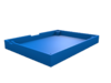
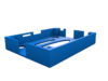
Cases
For Sale
- Full Case
- Full Case + Lure
Buildable
- Plexiglass
3D Printable
- Half cases
- Full cases
-
 Rom Hartmann's
- Paul Cox's Calamari LSE lure + HSE lure (Silverjaw or Jetsam) + PCI-E case
-


Accessories (Lures)
Lures are accessory boards that attach to the MinnowBoard-MAX and provide additional functionality. Lures are owned and supported by their respective owners and manufacturers. Information on Lures can be found on the MinnowBoard MAX Lure wiki page.
Known Issues
MinnowBoard-MAX Open Bugs (Bugzilla)
- Bugzilla:
We currently use the YoctoProject Bugzilla instance at http://bugzilla.yoctoproject.org - Bug Triage link can be found at: https://wiki.yoctoproject.org/wiki/Minnow_Bug_Triage
Weak HDMI signal causing some monitors to not work
The MinnowBoard MAX was found to be missing a level shifter on a differential pair for the HDMI signal. This causes our HDMI signal to be marginal. For many monitors this isn't an issue and many folks don't see this issue. However this does mean several things WILL NOT work currently:
- Non-passive adapters (un-powered VGA adapters being the big one)
- Some HDMI Monitors
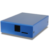
If you require a monitor to work, but it's not there is a work around that seems to resolve the issue for most folks. Specifically placing a POWERED HDMI switch between the MinnowBoard MAX and the display offsets the missing level shifter, as most powered HDMI switches do their own level shifting.
Bugzilla #7027 has more specific technical details about the issue
MinnowBoard MAX not booting: only one blue LED (D1) on, other (D2) is off
The MinnowBoard MAX does not have over-voltage protection; accidentally using a 12-volt power supply will likely result in a pop and smoke, and after that only one LED lights the the board fails to boot. The D2 blue LED indicates "Power OK". Developers have reported replacing the damaged Power Controller IC (U35) with a new part (inexpensive and widely available: NUVOTON, part# NCT3012S TR) has returned their board to a working state. Note this requires delicate soldering skills and could further damage the board if done incorrectly, and attempting this fix will almost certainly VOID YOUR WARRANTY
CPU Strapping issues
Some of the pins on the LSE and HSE, specifically those when switched into GPIO mode, can alter the way the CPU attempts to boot. In some cases the changes can prevent the system from successfully booting.
- LSE - Pin 16 - GPIO_I2S_FRM
- If set as GPIO (not native function) and pin is held low, de-selects SPI boot flash and firmware is not actually read from the on-board SPI flash
When using these pins, particularly on Lures, please be aware of the limitations.
LSE Pin 26 Change notification
Pin 26 on the Low Speed Expansion connector was intended to provide a good MCLK (Master Clock) for I2S functionality, however the pin that was chosen originally does not actually meet this need. In a later revision of the board (A4 onwards) this signal will be replaced with one that will provide a good MCLK. If you make use of pin 26, software and hardware may need to be updated once the A4, or later, designs are available. (There is currently no ETA for the A4 boards, and this is being mentioned just so people are aware of the impending change.)
Plate over High Speed Expansion Headers
There is an issue for some boards manufactured in early 2015: a protective metal plate (used during the manufacturing process for the pick-and-place machine) may have been left covering the High Speed Expansion Headers (HSE) on the bottom of the board. You should remove the metal plate if it's still there.
| Here's the HSE connector with the manufacturing cover that should be removed: |
and here's what the connector should look like without the manufacturing connector: | |
|---|---|---|
 |

|
Firmware
See the bug list, linked above.
NVRam issue
There are some reports of the UEFI firmware getting corrupted for firmware releases before 0.71. Symptoms include boot failure with no HDMI display output and both board LEDs are on. This problem has been fixed in firmware release 0.71 and above. Please update your firmware to the latest release.
Monitors
There is an issue with regards to some monitors not being able to display from the MinnowBoard MAX. Most monitors seem to be fine, but some will either completely not show a display (even at firmware boot-up) or may only show a display after the operating system is booting. This turns out to be an issue with HDMI vs. DVI detection and initialization. Firmware release 0.71 fixed this problem.
There have been additional reports saying some monitors may still not be working in the Firmware (UEFI shell), but are working once the OS (Linux) comes up. If you have a monitor that is having a problem please file a bug on our Bugzilla database and be sure to include the make, model, native resolution and the exact cabling used to connect the monitor to the MinnowBoard MAX
RTC
The Real-Time clock may not function correctly (when a battery is added) because resistor R278 (back side of the board) may be missing. Adding a 1K or 2K resistor should resolve this.
USB
There is a potential issue when using a powered USB hub that (erroneously) provides power over the USB 3 or USB 2 input connector. This is in violation of the USB spec. If such a powered USB hub is used, the MinnowBoard MAX will use that as power; this will be rectified in a future revision of the MinnowBoard MAX.
Hubs known to cause this:
- iXCC 7 Port USB 3.0 Hub
We recommend you check your powered USB hub to confirm that it does not provide power back to the board, as described. If you have a hub that is doing this, please report it here and either stop using it, or use it with its external power turned off.
NOTE: This is not an indication that hubs do not work, or that USB does not work. This is merely an indication that some powered hubs violate the USB spec, and there is a flaw (a diode should be added) in the MinnowBoard MAX design.
Another issue might appear if a wireless USB dongle operating at 2.4 GHz (e.g., a wireless receiver for input devices) is connected to the USB2.0 port together with an USB3.0 device attached to the USB3.0 host connector. In this case the device connected to the USB dongle can become unresponsive due to radio frequency interference form the USB3.0 connection. A solution is to use an extension cable or hub to move the the dongle further away from the board NOTE: This interference problem seems to be a general USB3.0 issue. Information on this can be found at Intel.com
UART dies with "Too much work for irq"
This is bug 6280. A temporary fix is to set the receive trigger on the UART to 1 byte. This can be done through the sysfs interface as follows:
echo 1 > /sys/class/tty/ttyS0/rx_trig_bytes
This can be applied on startup through init scripts, and since it only affects the receive side it should not affect boot times.
Export Information
MinnowBoard MAX Dual Core (E3825) w/ 2GB RAM
- Export Control Classification Number (ECCN) = 5A002.a.1
- CCATS number = G143235
- ENC is Unrestricted