Check out the new MinnowBoard.org website for the most up-to-date information on the MinnowBoard Turbot and the MinnowBoard.org Community.
Projects/Maker Slideshow
Contents
Minnowboard Slideshow
Aside from being a full computer on its own, the MinnowBoard may also function as a dedicated device.
For this tutorial, we'll demonstrate how to serve up a slideshow on a dedicated display. This is an intermediate-level project with several interacting components, including 14 GPIO pins on the MinnowBoard. We'll be using the SPI interface as well as our standard GPIO to power a TFT LCD, a 16x2 char LCD, buttons and a potentiometer.
Difficulty
Materials
You'll need:
- MinnowBoard MAX with peripherals such as an microSD card with an image installed that has mraa installed
- A full-sized breadboard. You may want multiple smaller breadboards to space out components too if you wish
- A 16x2 char 3.3v parallel LCD
- A TFT LCD display (such as the ILI9341 TFT LCD)
- A 10K potentiometer
- 2 buttons
- 2 10K ohm resistors
- 16 M-F jumper cables
- 12 M-M jumper cables
Like the previous projects, you'll need a connection between your MinnowBoard either through SSH, a web interface or the serial connection.
Difficulty
It's important that you've at least read through the other projects to understand all the material you'll need to complete this project. If you haven't, go checkout these wiki pages:
char LCD: assembly and code
TFT LCD: assembly and code
Buttons: assembly and code
Part 1: Connect the 16x2 char LCD
Wiring
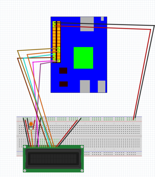
As mentioned in a previous project, when connecting the 16x2 char LCD, you'll need a total of 6 GPIO pins on the MinnowBoard to support the display. The recommended connection information is presented in the header to the char LCD library file ada_lcd.py as seen here:
# SETUP:
# MinnowBoard pin 26 --> ADA_LCD pin 4
# MinnowBoard pin 25 --> ADA_LCD pin 6
# MinnowBoard pin 23 --> ADA_LCD pin 11
# MinnowBoard pin 21 --> ADA_LCD pin 12
# MinnowBoard pin 20 --> ADA_LCD pin 14
# MinnowBoard pin 18 --> ADA_LCD pin 13
# -------ADA_LCD Additional Pins:-------
# ADA_LCD pin 1 --> GND
# ADA_LCD pin 2 --> PWR 5V
# ADA_LCD pin 3 --> analog data in (potentiometer)
# ADA_LCD pin 5 --> GND
# ADA_LCD pin 15 --> PWR 5V
# ADA_LCD pin 16 --> GND
A detailed schematic is here:
This include the potentiometer configuration and the ground and power. Do the Minnow #1 and #3 GND and 5v PWR last, and the screen should light up when you make those connections. To test out the screen, try rotating the potentiometer to adjust the gamma until you can see a row of white boxes. If you can't, double check your wiring.
Code
You only need two files to run the 16x2 char LCD successfully, assuming you're running on an image with Python and mraa installed like we have before. With the ada_lcd.py file, you can run the screen with just a bit of extra Python. #Insert Github link to final code
from ada_lcd import *
lcd = ADA_LCD()
lcd.clear()
lcd.message("Hello!")
If all worked, you can see the text on your screen! You might need to adjust the gamma to get a better view using the potentiometer. If nothing happened, review the wiring.
Part 2: Connect control buttons
Wiring
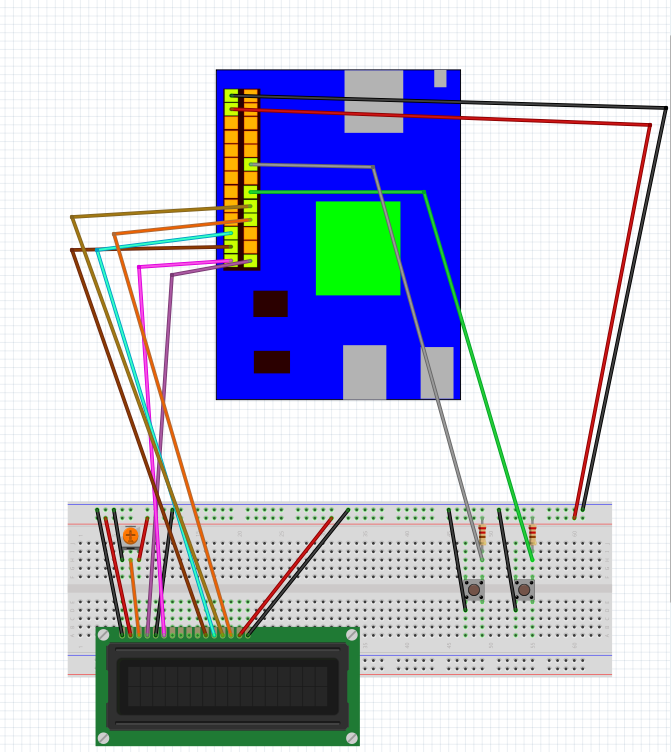
Two simple buttons will be used to navigate the slideshow. Wiring buttons is straightforward, as seen here with the LCD:
As you might expect, these GPIO pins will be configured to read IN.
Code
With the buttons and the char LCD installed, you can test them both out with the slideshow program. As before, you'll need to have the following files in your directory:
- slideshow.py (the slideshow implementation)
- ada_lcd.py (char LCD library)
- ILI9341.py (TFT LCD library)
- Adafruit_Python_GPIO (cross-platform GPIO library)
Additionally, you'll need this Python library:
- Python imaging library (Python library for processing images)
You'll need to create a directory and populate it with images. You can use any directory with images, the python script will filter out non-image files. Once you picked one, run the script like so:
python slideshow.py path_to_images/
where path_to_images/ is the location of your image directory. You should see something like this on the char LCD:
Image 1 of 4
mypicture.png
Of course, the picture name will be your filenames, and the number of images remaining will match the number of image files in your directory. Press the buttons to navigate through your images, you'll see the char LCD update the display.
Part 3: Connect TFT LCD
Wiring
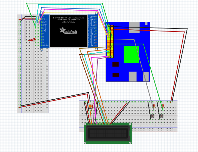
Now we'll want to see the images we have in the directory. For that we'll need to connect the TFT LCD, shown here connected to the Minnowboard SPI interface with all the other devices:
Here's an overview of the entire system:
With the whole system wired together.
Code
First off, make sure you've got the SPI driver installed. If you don't, go check out this section for detailed instructions. It's easy if you've got the Python package!
The only real new code for this project is the slideshow code itself. We'll present the full code with line numbers. Walking through it, we see our initial imports referencing each part of the project.
  1 import time
  2 import sys
  3 import os
  4 import Image
  5 from ada_lcd import *
  6 import ILI9341 as TFT
  7 import GPIO as GPIO
  8 import GPIO.SPI as SPI
Once we have all our libraries, we need to make sure the user ran the program correctly, that is specifying an image directory as an argument to the script:
 9 # If this runs, there were not enough arguments!
 10 if (len(sys.argv) < 2 ):
 11     print "Usage: python slideshow.py [image directory]"
 12     exit(1)
 13
Now we'll need to create the GPIO interface. These lines do just that, allowing the GPIO library to detect the MinnowBoard MAX and setup our two button pins. Remember to change these values if you've deviated from the diagram above, and you've put the buttons on a different pin.
 14 myGPIO = GPIO.get_platform_gpio()
 15
 16 myGPIO.setup(12,GPIO.IN)
 17 myGPIO.setup(16,GPIO.IN)
Now we start up the 16x2 char LCD display.
 18 # Startup the display
 19 lcd = ADA_LCD()
 20 lcd.clear()
Now we'll set the variables for the TFT LCD display on the SPI bus. If you moved the pin for the D/C connection, make sure you change the value here! In the diagram above, it is connected to pin 10.
 21 # SPI values set here
 22 SPI_PORT = 0
 23 SPI_DEVICE = 0
 24 SPEED = 16000000
 25 DC = 10
 26 RST = 14
Now we need to look at the provided directory and check for images. We'll put all the valid images in a list to iterate through
 27 # rawList contains all the files in the directory, imageList contains only image files
 28 imageList = []
 29 rawList = os.listdir(sys.argv[1])
 30 for i in range(0,len(rawList)):
 31     if (rawList[i].lower().endswith(('.png', '.jpg', '.jpeg', '.gif'))==True):
 32         imageList.append(sys.argv[1] + "/" + rawList[i])
 33 # No images? Better exit now!
 34 if len(imageList)==0:
 35     print "No images found!"
 36     exit(1)
 37
If we got to this point, we have a list of images. Now we'll initialize a counter variable to track where we are in the list and start up the TFT LCD display.
 38 count = 0
 39
 40 disp = TFT.ILI9341(DC, rst=RST, spi=SPI.SpiDev(SPI_PORT,SPI_DEVICE,SPEED))
 41 disp.begin()
 42
Now for the actual loop. Lots of stuff happens here, so here's a list:
- Clear the LCD display and write the name and ordered location of the upcoming image
- Try to open an image
- If we fail to open the file, print an error message to the LCD display
- If we failed, open up the next file in the list. If we're at the end, restart at the beginning.
- Display the image on the TFT LCD
 43 while True:
 44     lcd.clear()
 45     time.sleep(0.25)
 46     message = " Image " + str(count+1) + " of " + str(len(imageList)) + "\n" + imageList[count][len(sys.argv[1]):]
 47     lcd.message(message)
 48     lcd.scroll()
 49     try:
 50         image = Image.open(imageList[count])
 51     except(IOError):
 52         lcd.clear()
 53         time.sleep(0.25)
 54         message = " ERR: " + str(count+1) + " of " + str(len(imageList)) + "\n" + imageList[count][len(sys.argv[1]):]
 55         lcd.scroll()
 56         lcd.message(message)
 57         if(count == len(imageList)-1):
 58             image = Image.open(imageList[0])
 59         else:
 60             image = Image.open(imageList[count+1])
 61
 62     image = image.rotate(90).resize((240, 320))
 63     disp.display(image)
After displaying an image, we wait for the user to press a button to change which image we're on. We wait forever in another loop for one of the buttons to be pressed. Once we do, we change the counter variable and go back to the top. We also have another interrupt check here to handle the user exiting the program with Ctrl-C, where we print another message to the char LCD screen and stop the program.
 64     # Everything here is still in the loop from before
 65     try:
 66         while True:
 67             if (myGPIO.input(12) != 1 and count != 0):
 68                 count = count - 1
 69                 break
 70             if (myGPIO.input(16) != 1 and count != len(imageList)-1):
 71                 count = count + 1
 72                 break
 73     except (KeyboardInterrupt):
 74         lcd.clear()
 75         lcd.message("Terminated")
 76         print
 77         exit(0)
That's it! Just run the program, specifying an image directory, and you'll see it appear on screen. You can navigate left and right using the buttons. To stop the program, go to the terminal and enter Ctrl-C to interrupt it.
Files
The files can be found here at this repo for cloning. To install them on your device, run
python setup.py install


